With increase in line length and speed of modern continuous strip finishing lines, the lateral movement of strip becomes severe which necessitates of intermediate guiding system. The primary purpose of intermediate guiding is to maintain the strip approximately in the center of the line.
Unlike the Intermediate guiding system, in Uncoiler & Recoiler guiding system, the strip is corrected by the position error & rather the Uncoiler & Recoiler is continuously aligned to maintain the constant position of the strip below the sensor.
The different guiding systems presently used in the industry are-
Today all the automatic guide control systems are based on the closed loop systems with very good quality electronic signal processor, valve drivers and a feedback system from the field.
Unlike the Intermediate guiding system, in recoiler guiding system, the strip is not corrected by the position error & rather the recoiler is continuously aligned to the position of the strip.
For obtaining better Recoiler guiding performance, the Recoiler must follow in perfect unison with sensor signal. The sensor has to be located just after the deflector roll before the Recoiler. The sufficient wrap angle of the strip on the deflector roll shall avoid lateral slippage of the strip as the Recoiler slides in its base.
For a Recoiler guiding application the Recoiler has to move in synchronism & the shifting is proportional to the lateral shift of the strip. The synchronism of recoiler & sensor is achieved in two ways.
The sensor is coupled with the sliding recoiler frame by using a long steel arm. Depending on the distance between the last fixed idle roller and the mandrel, length of the steel arm is decided. In this type of system the shift in the strip position will create a variation of sensor signal. The error generated will move the recoiler to a new position of strip & the error signal will become null only when the sensor connected to the recoiler gets covered by strip again. This limits the system functioning gain to a lower value & hence there is a limitation of using this method for higher line speeds.
In this method of coupling the sensor is electronically coupled with recoiler by comparing the feedback signals of both. The sensor is fitted on a motorized positioner.
The Displacement of sensor w.r.t. shift of the strip, is measured by using a high-resolution encoder. This displacement will be compared with the actual movement of the recoiler by using a linear position transducer feedback. Because of this closed loop, the recoiler will move in synchronization with the sensor
Unlike the Intermediate guiding system, in uncoiler guiding system, the strip is corrected by the position error & rather the uncoiler is continuously aligned to maintain the constant position of the strip below the sensor.
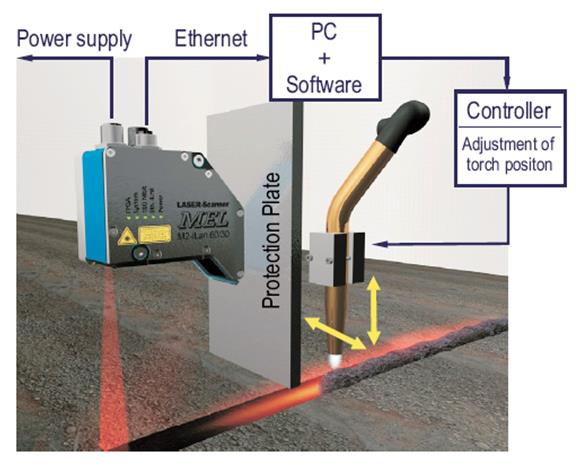
For obtaining better uncoiler guiding performance, the uncoiler must follow in perfect unison with sensor signal. The sensor to be located just sfter the deflector roll after the uncoiler. The sufficient wrap angle of the strip on the deflector roll shall avoid lateral slippage of the strip as the uncoiler slides in its base.
For a uncoiler guiding application the uncoiler has to move in synchronism & the shifting is proportional to the lateral shift of the strip. The synchronism of uncoiler & sensor signal is achieved as follows. .
In this method of coupling the sensor is electronically locked with the strip edge. This locking is done either by seeking the sensor to the edge of the sheet, or by locating the sensor at a 
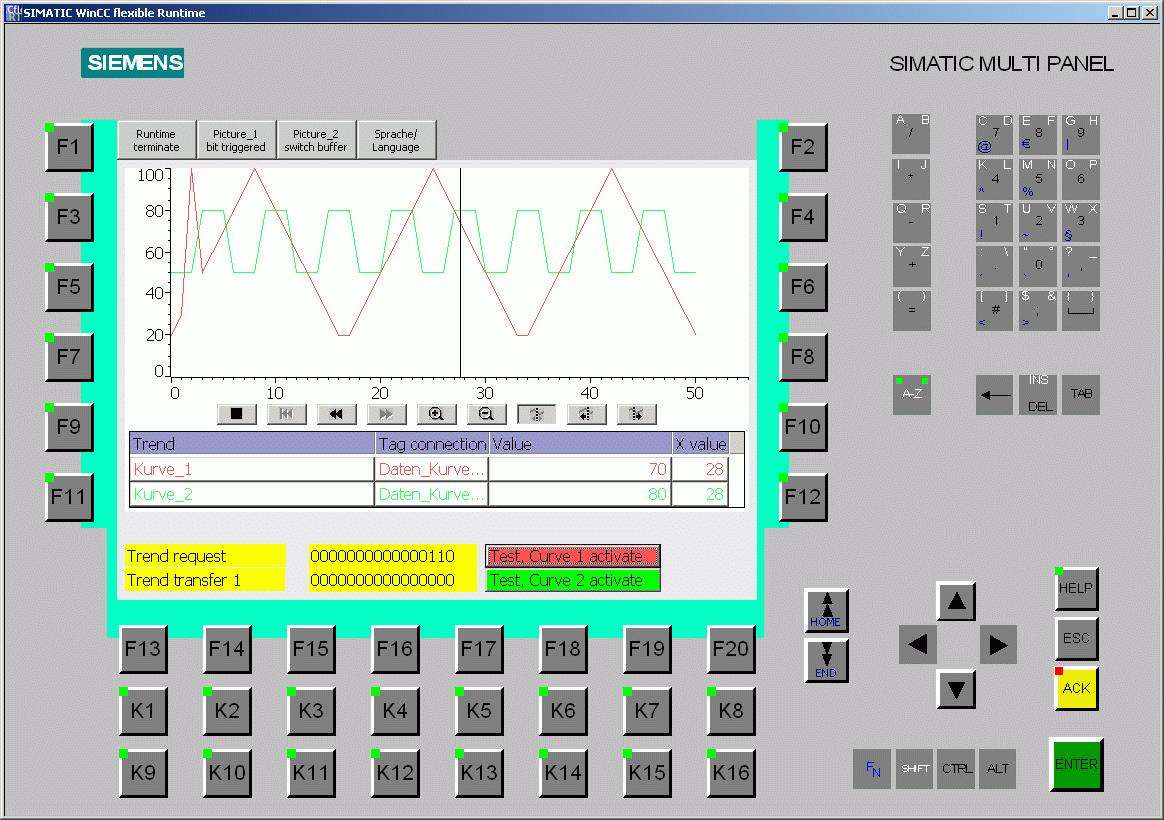
particular distance from the line center. This can be done by entering the distance through the operator interface. Even the scrap width can be inserted in the operator interface.
The system can be operated in AUTO mode in two ways.
In this case the operator will feed the value of desired output strip width in mm and scrap width in mm on drive side or operator side depending on which edge the sensor is sensing. So once the position command is given to the sensor it will position itself at a distance say X mm from line center , where X= (o/p strip width ) / 2 + scrap width.
Now the system will control uncoiler position accordingly to control strip position at cutter.
In this case the operator will feed the strip and will give seek command to the sensor. The sensor will find the strip edge and will get locked over there and will control the uncoiler to maintain the same strip position.
3.6" membrane keyboard with 10 freely configurable tactile keys ∙ Mono (STN, black/white) ∙ 87 mm x 31 mm (3.6") ∙ Backlight color programmed (white, green, yellow or red) ∙ Resolution: 240 x 80 ∙ 250 tags ∙ 50 process screens ∙ 200 alarms ∙ 25 curves ∙ 40 KB recipe memory ∙ 5 recipes, 20 data records, 20 entries
6" touch screen with 6 tactile keys ∙ Color (TFT, 256 colors) or Mono (STN, gray scales) ∙ 115.2 mm x 86.4 mm (5.7") Portrait or landscape ∙ Resolution: 320 x 240 ∙ 500 tags ∙ 50 process screens ∙ 200 alarms ∙ 25 curves ∙ 40 KB recipe memory ∙ 5 recipes, 20 data records, 20 entries Product overview 1.5 Basic HMI panels S7-1200 Programmable controller System Manual, 04/2012, A5E02486680-06 27 Basic HMI Panel Description Technical data
10" touch screen with 8 tactile keys ∙ Color (TFT, 256 colors) ∙ 211.2 mm x 158.4 mm (10.4") ∙ Resolution: 640 x 480 ∙ 500 tags ∙ 50 process screens ∙ 200 alarms ∙ 25 curves ∙ 40 KB recipe memory ∙ 5 recipes, 20 data records, 20 entries TP 1500 Basic PN
15" touch screen ∙ Color (TFT, 256 colors) ∙ 304.1 mm x 228.1 mm (15.1") ∙ Resolution: 1024 x 768 ∙ 500 tags ∙ 50 process screens ∙ 200 alarms ∙ 25 curves ∙ 40 KB recipe memory (integrated flash) ∙ 5 recipes, 20 data records, 20 entries
Wenglor MEL Sensors combines the best know-how from Opto Electronics, modern image processing and the experience of more than 20 years in the measuring technology